
To perform the gearbox speed calculation, you need to divide the input speed specified on the electric motor's nameplate by the gear ratio of the gearbox. Assuming your motor rotates at 1400 rpm and the gearbox you use has a ratio of 10, the speed you will obtain from the output shaft will be 140 rpm. This basic mathematical operation is based on the principle of reducing the high speed at the input shaft through gear mechanisms while increasing torque, allowing you to find the ideal speed required by the system.
When establishing the mechanical balance of the system, it is not only important to reduce speed but also to correctly analyze the ratio between the gears. This relationship between the small gear on the input shaft and the larger gear on the output side creates a power transmission that allows the motor to move much larger loads without strain. The calculation requires a proper understanding of the dynamics inside the gearbox to ensure efficient operation and energy savings.
To select the correct gearbox in industrial machines or special projects, you should also consider the torque requirement after determining the speed. An incorrect speed calculation can cause the motor to overheat, the system to lock up, or the mechanism to fail to deliver the desired performance. Therefore, after determining the output speed, you should also calculate the required rotational force of the system and integrate the most suitable power transmission component.
Gearbox Speed Calculation Formula and Logic

The gearbox speed calculation is essentially obtained by dividing the input speed from the electric motor by the ratio defined by the gearbox. The most critical data in this process are the rpm value written on the motor nameplate and the gear ratio specified in the gearbox catalog. Mathematically, when you divide the speed at the input shaft by the gear ratio, you obtain the net rotational speed from the output shaft. Although this process may seem complex, it is actually based on a fixed proportional logic and is the most reliable way to achieve the desired speed in machine design.
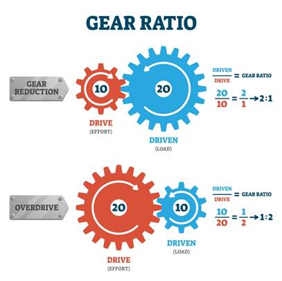
The operating principle of the system is based on the differences in diameter and tooth count of the gears inside. When a small gear connected to the input shaft drives a much larger gear, the speed decreases while the rotational force called torque increases proportionally. In other words, the decrease in speed is not a loss but a transformation of power into a usable form. Thanks to this mechanical conversion, high-speed but low-torque motors gain the capability to lift heavy loads or move conveyors slowly.
Accurate calculation is vital for the efficiency and longevity of industrial systems. An incorrectly determined ratio may cause the machine to operate too fast and become uncontrollable, or fail to produce the required force and stop. In engineering calculations, instead of focusing only on speed, performing a speed analysis by also considering the required torque ensures energy savings and prevents motor overheating.
How to Find Gearbox Ratio (Transmission Ratio)?
The value usually indicated by the letter "i" on the gearbox label clearly expresses the transmission ratio of the device. This value indicates how many rotations of the motor shaft are required for the gearbox shaft to complete one full rotation. If the label is unreadable or missing, you can verify it mathematically by dividing the known motor speed by the actual speed measured from the output shaft using a tachometer. The result reveals the system's speed reduction capacity and torque increase factor.
If you prefer a mechanical approach, you can perform an exact calculation based on gear teeth. By dividing the number of teeth of the large gear inside the gearbox by the number of teeth of the smaller driving gear, you obtain the transmission ratio.
In cases where you cannot perform physical counting or use measurement tools, the manual rotation technique can be applied. By marking both the input and output shafts, you rotate the input shaft by hand until the output shaft completes one full turn and count the rotations. The number of turns on the input shaft corresponding to one full turn of the output shaft directly gives the transmission ratio. This practical method, often used in maintenance and repair processes, allows quick solutions in the field without complex formulas.
Motor and Gearbox Output Speed Calculation with Examples
The main variables in the calculation process are always the nominal speed of the motor and the transmission ratio of the gearbox. Although the nameplate values of electric motors are generally standard, the wide range of gearbox ratios creates countless combinations. Achieving the correct result in this variety depends on placing the available data accurately into the formula. This stage, where theoretical knowledge is applied in practice, directly affects the success of machine design and system stability.
Let’s examine the first example using a commonly used 4-pole asynchronous motor running at 1400 rpm. When a gearbox with a transmission ratio of 20 is connected to this motor, the motion on the shaft slows down significantly while power transmission increases. Dividing 1400 by 20 gives a net output speed of 70 rpm. This scenario provides an ideal solution for systems such as packaging lines or conveyor belts that require moderate speed but continuous torque.
For applications requiring more precise and slower movement, consider a 6-pole motor running at 900 rpm paired with a gearbox with a ratio of 60. Dividing 900 by 60 results in 15 rpm. Such a low speed is typically preferred in industrial mixers, wastewater treatment tanks, or crane systems handling very heavy loads where maximum torque is required.
In engineering projects, the process sometimes works in reverse, and the required final speed is known in advance. For example, if the system must rotate exactly at 100 rpm and you have a 3000 rpm motor in stock, determining the required transmission component is simple. By dividing 3000 by 100, you determine that a gearbox with a ratio of 30 is needed. This reverse calculation method is the most reliable way to select the correct equipment during the design phase.
These mathematical calculations provide precise results for systems directly connected to the mains frequency without a drive. However, if a speed control device (inverter) is used and the motor frequency is adjusted below or above 50 Hz, the input speed will change, and calculations must be revised accordingly. While mechanical losses are negligible in standard operations, considering even microscopic deviations is a professional approach in highly sensitive automation systems.
How to Calculate Speed in Pulley and Belt Systems?
In pulley mechanisms, speed change is entirely based on the physical ratio of diameters. The difference in diameter between the driving pulley connected to the motor and the driven pulley on the load shaft determines the final speed of the system. Instead of counting gear teeth, diameter values measured in millimeters or centimeters are used in the formula. Since the contact surface is not rigid like gears, slight differences may occur between theoretical and practical speeds due to belt elasticity, but the basic mathematical logic remains constant.
The steps to find the correct output speed in this system are as follows:
- Measure the diameter of the driving pulley connected to the motor shaft.
- Determine the diameter of the driven pulley on the load side.
- Note the rpm value specified on the motor nameplate.
- Multiply the driving pulley diameter by the motor speed.
- Divide the result by the diameter of the driven pulley.
- The final value indicates how many revolutions per minute the load-side shaft will rotate.
The success of the calculation in practice also depends on preventing belt slippage and ensuring proper tension. It should be noted that when power is transmitted from a smaller diameter to a larger one, speed decreases while torque increases significantly. Conversely, when motion is transferred from a larger pulley to a smaller one, speed increases but torque decreases. In engineering design, achieving the correct speed is not enough; torque balance must also be ensured to prevent the machine from stalling under load.
Gearbox Torque Calculation and Motor Power Relationship
The relationship between the power produced by the motor and the torque obtained from the shaft forms the core of mechanical systems. Electric motors inherently rotate at high speeds while producing relatively low torque. Gearboxes come into play by reducing speed mechanically and converting the lost speed energy into torque—a usable rotational force. Thanks to this inverse proportional principle, even a low-power motor can move tons of load when paired with the correct gear ratios.
In engineering calculations, the constant 9550 is used to quantify this transformation. By multiplying the motor power (kW) by this constant and dividing it by the output speed, you obtain the torque in Newton-meters (Nm). However, since this theoretical formula does not include friction losses, the efficiency coefficient of the gearbox must also be considered in real applications. This efficiency, which varies depending on gear type and quality, is the most critical parameter showing how much of the motor's power is converted into useful work.
One of the most common mistakes in system design is focusing only on the horsepower or kilowatt value of the motor. The actual required value is the torque needed to move the load. Choosing an excessively powerful motor leads to energy waste, while a system with insufficient torque calculation may lock during startup and cause motor failure. For an ideal power transmission, it is necessary to analyze the load's inertia and required force accurately and match the motor and gearbox accordingly.
